Protocol for Communicating Registration Transformations
Pairs of Image Volumes to be Registered
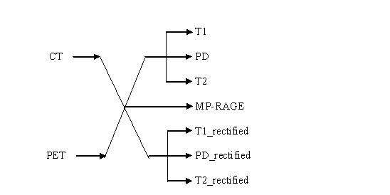
A given transformation maps points from one volume on the left, which we will call the “From” image, to one volume on the right, which we will call the “To” image.
Each transformation will be compared with a “gold standard” transformation for the corresponding From-To image pair. The gold standard will be a rigid body transformation. Thus it is expected that the transformations submitted by each team will also be rigid body transformations.
The Transformations Parameters
In choosing our method of communication, we want to minimize the chances for miscommunication and error. Therefore, we have chosen a set of parameters that is easy to understand, is easy to calculate, includes redundancy, and has limited error propagation. The redundancy provides us a chance to check for errors without compromising the blindedness of our study. The error check is based on the assumption of rigid body motion. The error propagation refers to the relationship between the inevitable round-off errors associated with specifying parameters via a finite number of symbols and the resulting positional error produced at every point within the image volume.
Our method is as follows: A transformation will be specified by the set of original positions and transformed positions for each of the centers of the voxels at the eight corners of the “From” volume. Each position will be specified by its three coordinates, x, y, and z, in millimeters. Thus a transformation will be specified by 48 numbers: three numbers for the original position and three for the transformed position for each of eight positions. We call the coordinates of a transformed position, new_x, new_y, and new_z. Each number will be specified in fixed point with four digits to the right of the decimal place (to 1/10,000 millimeter). An example of a complete specification is provided in the section below.
The origin of the coordinate reference system lies at the center of the first voxel in the voxel file. That file is described in Section 3.2 of the document PROTOCOLS FOR ACCESSING INFORMATION, Version 1.0 November 15, 1994. The x axis lies along the centers of the first row of voxels in the voxel file and is directed from the first voxel to the last on that row, the y axis lies along the centers of the first column and is directed from the first voxel to the last voxel on that column, and the z axis is perpendicular to the x and y axes and directed in the right-hand sense---from the first voxel in the file toward the first voxel in the last slice.
Consider for example the case described in the PROTOCOLS document, in which the number of rows, columns, and slices are, respecti
Display of slice 1---
1 2 3 4 5
6 7 8 9 10
11 12 13 14 15
16 17 18 19 20
21 22 23 24 25
26 27 28 29 30
The origin of the coordinate system lies at the center of voxel 1.
The x axis is directed from the center of voxel 1 to the center of voxel 5.
The y axis is directed from the center of voxel 1 to the center of voxel 11.
The z axis is directed from the center of voxel 1 to the center of voxel 16.
(Note that the resultant coordinate system is right-handed.)
It should perhaps be emphasized that all coordinates are in units of millimeters, as opposed to numbers of voxels or pixels. The conversion from voxel dimensions to millimeters should be done independently of the transformation that is being communicated. That conversion should be based on the pixel dimensions and slice thicknesses given in the header.ascii files associated with each image.bin file (see the PROTOCOLS document). Since all coordinates are in the same units, there is no need to include scale factors in the transformation to account for differences in voxel size. Indeed it would be wrong to do so.
Template for the Transformation Parameters
Transformation Parameters
Site:
Date: 12 December 1994
Patient number: 001
From: CT
To: MR-T1
2 333.9870 0.0000 0.0000 339.1179 -60.8117 -19.2691
3 0.0000 333.9870 0.0000 33.5198 299.5603 -16.2633
4 333.9870 333.9870 0.0000 366.5048 272.1734 -15.2613
5 0.0000 0.0000 112.0000 5.6848 -34.7688 91.7289
6 333.9870 0.0000 112.0000 338.6699 -62.1557 92.7309
7 0.0000 333.9870 112.0000 33.0718 298.2163 95.7367
8 333.9870 333.9870 112.0000 366.0568 270.8293 96.7387
(All distances are in millimeters.)
-----------------------------------------------------------------------------------
Error Checking
We wish to keep such errors an order of magnitude below the effects that we are measuring, namely positional differences between the retrospective registration and the gold standard prospective registration. Since the gold standard is itself in error by at least 0.1 mm, we will consider any RMS error of less than 0.01 mm to be acceptable. If the error is 0.01 mm or greater, we will alert the investigators and give them the option of checking for errors and resubmitting the transformation. We emphasize that this procedure does not compromise the blindedness of the study, since this error is unrelated to the registration error that we are attempting to assess and does not involve a comparison with the gold standard registration. It is merely an assessment of whether or not the submitted transformation is a rigid body transformation.
A benefit of having eight points instead of the minimum of three is that it greatly reduces the probability that erroneous numbers will produce a rigid transformation. We chose the particular number eight because it is larger than three and it equals the number of corners. The use of all the corners has a nice property regarding error propagation. Any error in the specification of the corner positions will produce errors in the transformation that will affect the interior positions. For any linear interpolant (including in particular rigid body motion) the error that propagates from the corners to the interior of the volume will be no greater than the largest error at the corners. Thus, each site can be sure that the rigid body transformation that they specify is in fact equal throughout the volume to the one that they have derived to within the accuracy of the corner positions.
In order to prevent, as much as possible, errors in the conversion from the coordinate and transform representation system used by investigators and that used for data submission, on receipt of a transformation table we will generate a reformatted image volume according to the transformation specified by the table. These images will be made accessible only to the investigator(s) who submitted the transform: their location and access method will be given to the submitting site. We suggest that all investigators check the reformatted volumes produced by their registration against the volume we provide, to insure that the intended transformation has been given to us.